|
On-line demos Project manager |
Editors Debugger |
White paper Brochure |
  |

|
|||||
|
Editors UML class diagram Business libraries are defined with the class diagram and organized in packages. Traditional UML classes are preferably used to define static objects and SDL classes are preferably used to define dynamic objects such as processes or functional blocks. 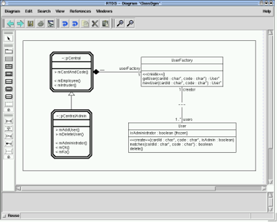
Code generator generates C++ stubs out of passive classes. UML deployment diagram The overall SDL-RT system can be distributed on several nodes, components, and executables. Distribution is specified with the UML deployment diagram and code generation will automatically generate the necessary information to handle communication between nodes, components, and executables. 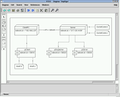
UML use case diagram A use case diagram shows the relationship among actors and use cases within a system. 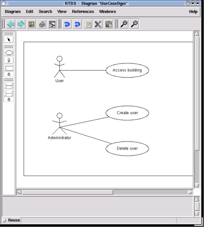
Text editor Since C and C++ languages are embedded in SDL-RT, parts of the design can be fully written in C. A text editor is integrated in the tool with all the classical features a C developer can expect. The same editor can be used to set breakpoints, step, or define watch variables when debugging the system. 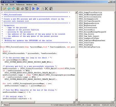 Data dictionnary An internal data dictionnary handles information in the SDL-RT system in a consistent way. It provides three major features:
|
SDL-RT editor SDL-RT editor is an easy to use, intuitive interface to design SDL-RT systems. It includes all can be expected of such an editor such as : copy/paste, unlimited undo/redo, automatic symbol insertion, syntactic and semantic verification, and on-the-fly SDL-RT syntax explanations. The diagrams include a page setup to guarantee the final diagram will be printable. Diagrams can also be saved as PNG or JPEG files.  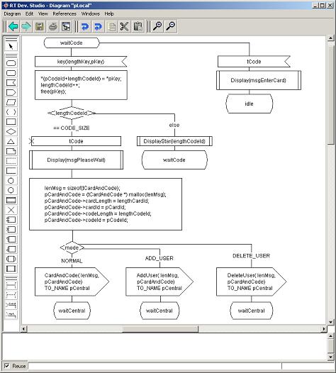
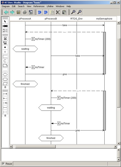
SDL-RT MSC representation provides a detailed description of the dynamic behavior of the system. Each task of the RTOS is seen as a line on the diagram where time flows from top to bottom. As with SDL-RT, key events in the system have a graphical representation such as :
 MSC Diff The MSC Diff fonctionnality checks the differences between two MSCs. It is therefore possible to check:
HMSC editor High level Message Sequence Chart editor allows to organize MSC diagrams and define how they relate to one another: MSCs can be executed in parallel or in sequence. 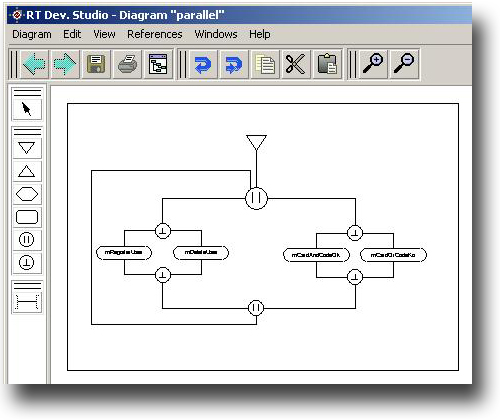
|