|
On-line demos Project manager |
SDL Z.100 SDL-RT |
UML Brochures |
  |

|
|||||
|
UML support UML class diagram Business libraries are defined with the class diagram and organized in packages. Traditional UML classes are preferably used to define static objects and SDL classes are preferably used to define dynamic objects such as processes or functional blocks. 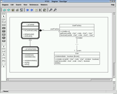
Code generator generates C++ stubs out of passive classes. UML use case diagram A use case diagram shows the relationship among actors and use cases within a system. 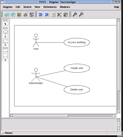
State chart RTDS G3 state machine description is based on SDL graphical representation because it is much more detailed than the classical UML state chart. |
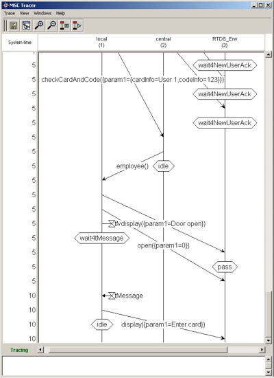
UML Sequence Diagram are equivalent to SDL-RT MSC (Message Sequence Chart). It provides a detailed description of the dynamic behavior of the system. Each object, semaphore or task of the RTOS is seen as a line on the diagram where time flows from top to bottom. When associated with SDL-RT, key events in the system have a graphical representation such as :
 UML deployment diagram The overall SDL-RT system can be distributed on several nodes, components, and executables. Distribution is specified with the UML deployment diagram and code generation will automatically generate the necessary information to handle communication between nodes, components, and executables. 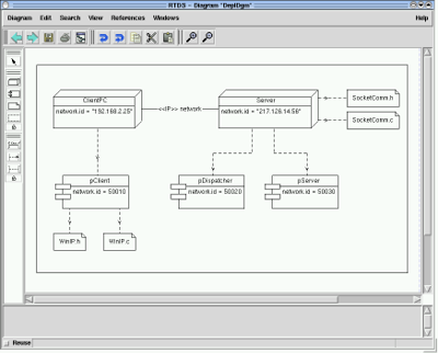
|